Purpose of the excitation system STR(N)
Static thyristor excitation systems of the series ST(P,H)-1P-XXX-XXX-UHL4 with digital control and excitation regulation are designed to supply automatically controlled rectified current of the excitation windings of hydro generators and turbine generators of medium power.
Excitation systems can be used for both newly developed and reconstructed generators.
The excitation system is designed to operate under the following conditions:
- height above sea level not more than 1000 m;
- normal ambient air temperature from +5°C to +40°C;
- relative humidity not more than 98% at a temperature of +35 ° C.
The environment is non-explosive, not containing conductive dust in concentrations that reduce the level of insulation in unacceptable limits.
Group of operating conditions in terms of exposure to mechanical environmental factors M39 according to GOST 17516.1-90. In this case, the vibration of the floor, where the excitation system is installed, should not exceed the acceleration of 2.5 m / s in the frequency range of 0.5-100 Hz.
The output parameters of current and voltage excitation systems are selected in accordance with GOST 18142.1-80, taking into account the requirements of GOST 21558-2000. At the request of the customer, other values of these parameters can be set.
1. TECHNICAL DATA
1.1 The main technical data of hydro generators and replaceable excitation systems for the parameters of hydro generators of the Knyazhegub HPP are given below.
| Name of the parameter | Meaning | ||||
| 1. Generator station number | 1 | 2 | 3 | 4 | |
| 2. Type of generator | CB 850/120-60 | ||||
| 3. Manufacturer | Electrosila | ||||
| 4. Year of release | 1953 | 1953 | |||
| 5. Generator power, MVA/MW | 40/35 | ||||
| 6. Nominal stator voltage, kV | 10.5 | ||||
| 7. Nominal stator current, A | 2200 | ||||
| 8. Nominal rotor voltage, B | 235 | 190 | |||
| 9. Nominal rotor current, A | 1250 | 1195 | 1195 | 1195 | |
| 10. Type of excitation system | B183/36-12 | ||||
| 11. Power, kW | 320 | ||||
| 12. Anchor voltage, B | 250 | ||||
| 13. Anchor current, A | 1280 | ||||
| 14. Excitation | spontaneousness | ||||
| 15. Regulator type | EPA | ||||
1.2. In accordance with the required parameters of excitation of hydro generators, a static thyristor excitation system of the type ST(R,H)-1P-300-1400 UHL 4 is proposed. The system is performed according to the scheme of self-excitation and contains two transforming and regulating channels, which allows you to abandon the need to have a backup excitation system. The table shows the main parameters and characteristics of the proposed excitation system.
| Name of the parameter | Meaning | |
| 1. Nominal excitation current, A | 1400 | |
| 2. Nominal excitation voltage, B | 300 | |
| 3. The ceiling on the excitation voltage is not less, o.e. | 2.5 | |
| 4. Excitation ceiling at least, o.e. | 2.0 | |
| 5. The duration of the flow of the forcing current is not less, c | 50 | |
| 6. The speed of the excitation system, the effect of the excitation system is no more, c. | 0.07 | |
| 7. Network voltage frequency, Hz | 50 | |
| 8. Power supply voltage of DC circuits, B Permissible long-term deviation of voltage, % |
220 +10, -15 |
|
| 9. AC supply voltage, B Permissible change in AC supply voltage, % long-term |
380 +10, -20 |
|
| 10. Nominal voltage of stator voltage measurement circuits (current value), B | 105 |
|
| 11. Nominal current on circuits measuring the current of the stator and rotor (current value), A | 5 |
|
| 12. Consumption of power by own needs: (a) from a network of 380 V, 50 Hz AC, kW, not more than: long-term short-term (at the time of initial excitation 15 c) (b) from 220 V DC, kW, not more than long-term short-term, no more than 50 s less than 15 seconds c) from measuring voltage transformers (per phase), VA, no more d) from measuring current transformers (per phase), VA, no more |
0. 5 3.0 - 30 0.55 1. 0 3. 0 10.0 10.0 |
|
| 13. Efficiency factor, % | 93.0 | |
| 14. Average sound level at a distance of 1 m from the circuit of the equipment, dBA, not more | 75 |
The excitation system provides the following operating modes and excitation parameters:
- initial excitation from the source of direct current 220V (battery) and from the network of own needs of the station 380V, 50Hz;
- idle;
- incorporation into the network by the method of accurate (automatic and manual) synchronization;
- inclusion in the network by self-synchronization (with a slide of no more than 5%);
- work in the combined and autonomous power systems with loads from idling to nominal, as well as with overloads corresponding to GOST 183-74 and GOST 533-85;
- stable regulation of excitation at sharply variable loads, up to individual load surges caused by simultaneous inclusion of asynchronous motors with a squirrel-cage rotor with a total power of up to 30% of the rated power of the generator;
- stop the unit in normal and emergency modes;
- forcing excitation with a customizable forcing setting and with the possibility of dosed exposure to it from emergency automation devices;
- excitation in case of disturbances in the power system, causing a corresponding decrease or increase in the voltage on the tires of the station or generator in relation to a given static characteristic;
- excitation (quenching of the field) during normal stop of the generator by transferring the thyristor converter (hereinafter the converter) to the inverter mode;
- field suppression in emergency modes when protecting by transferring the converter to the inverter mode;
- proportional-integral-differential regulation of the stator voltage according to its deviation from the given static characteristic of the generator. To expand the areas of stability when working in the network under load and improve the quality of transient processes can be stabilized by derivatives of the voltage of the stator and current of the generator rotor. At the same time, the following maximum coefficients are provided through regulatory channels:
- according to the proportional channel of deviation of voltage of the stator of the generator KOH= 120 units e.g. locomotive. /e.g. stator (in step 1);
- on the channel of the first derivative of the voltage of the stator of the generator Ku = 20 units. /e.g. stator/s (in step 0.001);
- on the channel of the first derivative of the rotor current of the generator Kiif = 10 units. /Uc. current bp./s. (with step 1).
Note: for the relative unit of stator voltage, voltage and excitation current, the corresponding nominal values of the generator are taken.
- maintaining the voltage at the outputs of the generator in accordance with the specified setting with an accuracy of ± 0.5% relative to the specified static characteristic. In this case, the amount of regulation statism can be selected in the range from 0 to ± 10%;
- stable distribution of reactive power between generators of comparable power, combined at the level of generator voltage, without the use of group regulation or equalization links;
- unloading the generator on reactive power with an accuracy of ± 5% of the nominal value when it is turned off;
- software initial excitation up to 95±5% of the nominal voltage of the generator and excitation during a planned stop;
- local and remote change of the voltage regulator setting in the range from 80 to 110% of the nominal voltage of the generator;
- limiting the excitation current to two times the rated excitation current of the generator without time exposure, as well as limiting the overload of the rotor during the dependent characteristic in accordance with the generator data;
- limiting the minimum excitation current to a value that does not allow the generator to enter the deep reactive power consumption mode (limiting the minimum rotor current at the nominal active load and the reactive power consumption corresponding to the cos j = 0.85);
- work with devices for group voltage regulation;
- stabilization of stator currents of parallel operating generator-transformer units combined on 110 kV tires by introducing statism;
- independence of the voltage at the outputs of the generator from the frequency in the range from 45 Hz and above, with a proportional reduction in voltage with a decrease in frequency below 45 Hz;
- protection of the system of excitation and winding of the rotor from overvoltages during field suppression of the rotor and self-synchronization;
- control and measurement of insulation of the rotor winding;
- registration of abnormal and emergency modes of operation of the excitation system;
- possibility of inclusion in the ACS TP HPP.
1.4 Excitation systems shall be provided with two autonomous and equivalent transducer/regulatory channels. Each channel contains a thyristor transducer, an automatic excitation regulator (ARV) with a pulse-phase thyristor control system. Any of the channels is able to independently provide all modes of operation of the generator, including the mode of forcing excitation.
One of the channels is in operation, the other is in a state of readiness. In the backup channel, the control pulses are blocked. In case of failure of the operating channel, a backup channel is introduced automatically or on the operator's command.
Thanks to automatic tracking, throws of excitation current when switching channels are excluded.
With the help of automatic switches and disconnectors on the sides of alternating and direct current, voltage can be removed from any converting and regulating channel for prevention or repair without interrupting the generator.
2. EQUIPMENT COMPOSITION
2.1. Dry transformer type DGH ("HELMKE", Germany), or another company.
One-way service initiation shield consisting of:
- two power thyristor sections (caskets) with built-in blocks of automatic regulators of excitation and control;
- distribution section (casket).
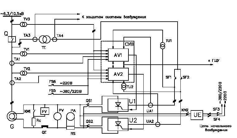
Static excitation system STS-2P-300-1400 UHL 4, circuit electrical functional
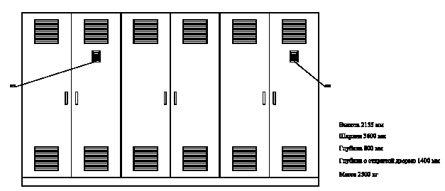
Static excitation system STS-2P-300-1400 UHL 4, general appearance and overall dimensions of the excitation shield
3. DESCRIPTION OF THE ESSENTIAL COMPONENT EXCITATION SYSTEMS
3.1. Thyristor sections
Thyristor sections (U1 and U2 in Figure 1) are made on the basis of a unified series of thyristor converters of the company "SIEI". The thyristors used in these transducers are characterized by very small losses and make it possible to perform the transducer when using forced cooling with one thyristor in the shoulder. At the same time, the converters are quite compact and technological during installation and maintenance.
Each thyristor section includes a thyristor converter made according to a three-phase bridge scheme.
The thyristor converter consists of three modules containing two thyristors each, relating to the anode and cathodic groups of the converter. Thyristor converters are equipped with fuses, RC-chains, blocks of terminal amplifiers, thermal sensors, etc.
Due to the presence of switches and disconnectors in AC and DC circuits, the thyristor section can be decommissioned for preventive and repair work. Thyristor modules are also easily detached for inspection and repair.
The thyristor sections are powered from the transformer through the QF1 and QF2 circuit breakers (see Figure 1).
3.2. Excitation control and regulation system (SMS)
Each transforming and regulating channel of the excitation system is equipped with its own automatic excitation regulator AV1 or AV2 (see figure 1), which perform all the functions of controlling, regulating, restricting and protecting its channel. The regulators are powered from the TE transformer through the matching transformers TU1 and TU2 and from the network of own needs 380V and the operative direct current 220V in case of loss of power to own needs.
Each regulator is equipped with a microprocessor unit that ensures the implementation of all algorithms for controlling and regulating, protecting and signaling the excitation system.
Algorithms of control and regulation are formed on the basis of the internal mathematical model of the generator. Recording and accumulation of parameters of the state of the excitation system allows you to derive them for analysis of transient and emergency processes. Each regulator provides local and remote control of excitation, and automatic channel switching in case of equipment failure of one of the thyristor sections.
3.3. Local government remote
The local control panel contains a programmable controller, display and keyboard. In doing so, it is capable of performing the following functions:
- introduction and correction of coefficients and constant time of regulators;
- introduction and correction of the statutes;
- review of variables and control parameters;
- control of the state of power chains and elements;
- control of serviceability of elements;
- automatic switching of conversion and control channels in case of failure of equipment of one of thyristor converters;
- visual display of current information on the display and storage of the previous (event diary), storage of information about the action of internal protections, excitation systems, as well as modification of monitoring and regulation parameters.
3.4. Protections
3.4.1. The excitation system provides the following protections:
- if both channels of regulation fail;
- rotor chains from closing to the ground (reducing insulation);
- rotor chains from overvoltages by means of a thyristor discharger;
- maximum current;
- from short circuit on dc tires;
- from loss of excitement;
- from short circuit on dc tires;
- from the unacceptable duration of forcing;
- from exceeding the maximum current;
- with unsuccessful inverting.
3.4.2. Operational quenching of the field during normal stop is performed by transferring thyristor transducers to the inverter mode. Extinguishing the rotor field in emergency modes under the action of any protection is performed by a field extinguishing switch (if any) and transferring thyristor converters to the inverter mode. Both methods of quenching are made mutually independent, and when quenching the field, the command is picked up until the end of the quenching process.
3.5. External commands and output signals
3.5.1. The excitation system provides the reception of the following basic relay commands from the unit control scheme by dry contacts designed for a voltage of 24 to 220V DC:
- excitement;
- position of the generator switch;
- frequency of rotation of the unit >=95% of the nominal value;
- excitation of "more";
- excitation of "less";
- precise synchronization;
- adjusting the generator voltage to the network voltage;
- разгрузка генератора по реактивной мощности до cos? = l;
- excitement;
- unit protection.
3.5.2. The excitation system provides the following main relay signals to the unit control system with dry contacts designed for a voltage from = 24 to 220V and a current of 0.5A. Active state of contacts - closed:
- channel 1 in operation;
- channel 1 is defective;
- channel 2 in operation;
- channel 2 is defective;
- work on a manual regulator;
- the end of the adjustment of the generator voltage to the mains voltage (sync resolution);
- the end of unloading of the generator on reactive power;
- work of the limiter of the maximum excitation current;
- work of the limiter of the minimum excitation current;
- malfunction of the excitation system;
- disconnection under the action of internal protections of the excitation system.
3.5.3. The excitation system provides, if necessary, the issuance of analog signals from rotor current and voltage sensors to the main control panel of the generator.
The excitation system provides technical means for transmitting information on the state of the excitation system equipment and its parameters via a digital interface to the unit control scheme. The content of messages and their formats are agreed at the stage of development of the ICS of the power unit.
4. SCHEMATIC AND STRUCTURAL FEATURES AND ADVANTAGES
4.1. Thyristor excitation system with one thyristor in the shoulder does not require expensive measures aimed at dividing currents between thyristors. The design is more compact and convenient for maintenance and repair.
4.2. The computational power of the microprocessors of the regulators allows to build the control processes in the most adequate way for alternating current machines.
4.3. In the control system, outputless elements and surface installation are widely used.
5. RELIABILITY INDICATORS
The excitation system provides the following reliability indicators:
| availability ratio, not less than % | 99.8.8 |
| average operating time for failure (disconnection of the generator from the network), at least hours | 60,000 |
| fixed resource between major repairs, years | 10 |
| average service life (from the start of operation to the failure of the equipment or part thereof, in which restoration is impractical), at least, years | 40 |