Purpose of the excitation control cabinet SHUV-2K
The microprocessor automatic excitation regulator of the SHUV series, manufactured by Energocomplekt JSC, is designed to supply automatically controlled current to the excitation windings of brushless turbine generator exciters and hydro generators with a capacity of 1.5 to 160 MW in all operating modes. The regulator performs all the functions of control, protection and alarm about the state of the excitation system.
excitation control cabinet SHUV can also be used to complete excitation systems of generators of other series and types, as well as in the reconstruction of electric, high-frequency and brushless excitation systems of generators, which have control and regulation equipment made on the basis of EPA panels, RVA-62 regulators, SDE-76 control stations, ARV-R devices, etc.
The automatic excitation regulator of the AVR excitation cabinet has been tested on the electrodynamic model of OJSC "NIIPT" (St. Petersburg) and has an expert opinion on the possibility of using generators of any power.
 |
 |
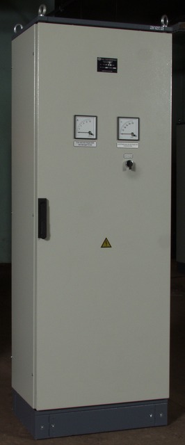
Appearance of the excitation cabinet SHUV-2K, (cabinet design) 100% reserve
The regulator is manufactured in the climatic version of the UHL and the placement category 4 with the following climatic factors:
- ambient temperature from +1 to +40 °C;
- height above sea level up to 3000 m;
- relative humidity not more than 80% at a temperature of +25 ° C.
According to the operating conditions in terms of mechanical factors, the regulator has a mechanical group M39, while the acceleration of vibration of the floor of the room should not be more than 2.5 m / s2 at frequencies in the range from 0.5 to 100 Hz, the degree of rigidity is 8. The degree of protection of the regulator is IP20, 23 or 54 according to GOST 14254-96.
The regulator provides
- operation of generators in modes:
- initial excitement,
- idle,
- inclusion in the network by methods of accurate synchronization and self-synchronization,
- network operation or autonomous load; - local or remote change of voltage setting at a rate of 0.5% per second in the range from 80 to 110%, relative to the nominal voltage of the generator;
- maintaining the voltage of the generator set by the installation with an accuracy of not less than 1% relative to the established static characteristic;
- independence of voltage at the outputs of the generator in idling mode when the frequency changes from 47 to 52 Hz;
- forcing the excitation current to the maximum multiplicity values during disturbances that caused a decrease in voltage at the outputs of the generator by 10-20% or more;
- automatic restriction of the excitation current when a two-fold value of the generator rotor current is reached;
- limiting the excitation current of the exciter by time-dependent characteristic in accordance with the data on generator overload;
- field suppression (excitation) of the generator by field suppression of the brushless exciter;
- programmatic initial excitation;
- stable regulation of the generator excitation current under abruptly variable loads, up to individual load discharges caused by the simultaneous inclusion of asynchronous motors with a total power of up to 30% of the rated power of the generator;
- limiting the minimum excitation current to a value that does not allow the generator to enter the deep reactive power consumption mode;
- stable distribution of reactive power without the use of group regulation or cross-leveling links between several simultaneously switched on at the level of generator voltage, the same type of generators of comparable power;
- unloading the generator on reactive power and disconnecting it from the network.
Composition
The brushless excitation system includes a brushless exciter installed on the shaft of the generator, a regulator and a transformer connected to the clamps of the generator stator. The regulator is a structurally completed unit, which includes: the power section and the control section. The general view of the regulator is given in Fig.1. Under operating conditions, the regulator unit can be placed in a separate cabinet or in one of the panels of the generator control shield.
Basic technical data
| Name of the parameter | Meaning |
| Nominal rectified current, A | 4 - 100 |
| Nominal rectified voltage, B | 36 - 250 |
| Multiplicity of forcing by the excitation current of the exciter, o.e., at least | 3 |
| Duration of overload at double current, with | 60 |
| Nominal power supply voltage of the power module, not more, B | 440 |
| Power module voltage frequency, Hz | 25-100 |
| Power supply voltage of control equipment, B | = 120 - 375 |
| Power consumption of power control equipment for food, W, no more | 100 |
| Nominal voltage of stator voltage measurement circuits, B | 105 |
| Power consumption from measuring current and voltage transformers per phase, VA, no more | 2 |