Purpose of a thyristor frequency converter TPU EK-AV6
The frequency converter (current inverter) EK-AV6-XX-SF-VX, manufactured by Energocomplekt JSC, is designed to control the acceleration speed of medium-voltage synchronous motors of mills (and other mechanisms with high starting torque) at a voltage of 3, 6, 10 kV.
The current inverter (IT) is implemented on two thyristor bridges turned on anti-parallel and connected to each other through DC circuits with a DC throttle, and to reduce the impact on the supply network, the mill current inverter is connected through a 3-phase reactor. The current inverter is used with an excitation system of the EX-SR type and controls the excitation of the electric motor of the mill via a digital channel. The current inverter can perform intermittent and continuous transfer of the mill to the electrical network.
The current inverter can transfer the motor to the network in two ways. Acceleration is slightly higher than the synchronous speed and switching to the network with a current-free pause. Or accurate synchronization with the network and translation without interruption of power of the engine (short-term parallel work with the network, 2 DC reactors are required on the bus +/- and output AC reactor).
The frequency converter (current inverter) EK-AV6-XX-SF-VX can be used to work with multiple mills.
The EK-AV6-XX-SF-VX does not require the installation of other equipment to reduce the negative effects of energy conversion on insulation of the motor windings.
The EK-AV6-XX-SF-VX is fully digitally controlled, can be used in automated manufacturing, controlled and monitored by a higher-level control system.
Basic technical data and characteristics
| Name of the parameter | Meaning |
| Nominal power output, kW | 4,000 |
| Nominal voltage, B | 6,000 |
| Nominal output current, A | 480 |
| Multiplicity of current overload, o.e. | 1.5 |
| Duration of overload (+50%), with | 120 |
| Frequency control range, Hz | 10. 50 |
| Carrier modulation frequency, Hz | 50 |
| Number of thyristors in the shoulder per 6kV phase (3.10) | 4 (3.6) |
| Nominal supply voltage of AC circuits (control section), B | 220 |
| Power consumption on AC circuits (control section), VA, no more | 1500 |
| Overall and connecting dimensions of the inverter with reactors (VhShG), mm | 2400x6000x2000 |
| Mass, kg | 4200 |
| Inverter dimensions (VhShG), mm | 2400x3200x1200 |
| Wardrobe mass, kg | 1600 |
| Overall and connecting dimensions of DC reactor (VhShG), mm | 2600x1800x1800000000000000000000 |
| Mass, kg | 1800 |
| Overall and connecting dimensions of LC filter (WhSH), mm | 1400x1500x1500x |
| Mass, kg | 800 |
| Climate performance and category of accommodation | UHL4 |
| Degree of protection of cabinets | IP40 |
| Degree of reactor protection | IP20 |

EK-AV6-4.0-SF-V6 UHL4, 4000 kW, 6 kV, with reactors
Structural circuit of the current inverter EK-AV6-4.0-SF-V6

Power circuit of the current inverter EK-AV6-4.0-SF-V6 UHL4, 4000 kW, 6 kV
EK-AV6 double service cabinets;
Protection of the power unit without the use of fuses;
The degree of protection of the shells from the facade IP 40.
Cooling is forced by air.
EK-AV6 provides smooth non-impact start, eliminating current throws.
The presence of an industrial communication interface.
The EK-AV6 has a galvanic decoupling of the power unit and control components.
Modular design of the converter provides fast maintenance and repair.
The control system of the current inverter EK-AV6 provides control of the launcher and high-voltage switching equipment, their diagnosis, display of the state of the equipment and archiving information on 50 events for all these parameters.
It is possible to integrate the control system of the launcher into the ICS of the upper level and an oscilloscope and a GSM modem for remote diagnostics of equipment can be installed at the request of the Customer.
To provide power to the equipment of the complex of technical means of the EK-AV6 control system, if necessary, a backup operational power supply system using uninterruptible power sources can be provided.
The current inverter EK-AV6-XX-SF-VX has a powerful microprocessor control system in combination with high-speed power modules, thanks to which it demonstrates the following advantages:
- smooth speed control over a wide range;
- smooth start and smooth stop of the engine;
- high accuracy of maintaining the technological parameter;
- ease of reconfiguration for a specific technical task;
- the ability to work under the control of the upper level ACSMS using the ModBus RTU, Profibus DP protocols.
When using the current inverter EK-AV6-4.0-SF-V6:
- provides a significant reduction in voltage drawdown in the supply network in comparison with direct start;
- possible regenerative and dynamic braking of the engine, as well as running out;
- it does not require the selection of special engines with an increased class of insulation, the heating of the engine does not go beyond the usual.
WORKING PRINCIPLE
To form the output voltage EK-AV6 consists of two thyristor bridges included according to the current inverter scheme. At the same time, the first bridge converts the 3-phase network into a constant voltage (to the DC reactor), and the second bridge works as a current inverter, which forms a three-phase current with the ability to regulate the amplitude and frequency.
Each thyristor bridge is assembled as a three-phase rectifier on thyristors according to the Larionov scheme. The first rectifier is attached to the windings of the 3-phase reactor to minimize the effect of harmonics arising when starting on the "network", and outputs to the DC-reactor to smooth out the pulsations of the rectified current. 4. The second inverter is connected between the DC circuits and the synchronous electric motor.
Each bridge is designed for full current and voltage, but usually only works until the electric motor is put on the grid. The current inverter to the output voltage of 3 and 10 kV contain respectively 3 and 6 thyristors in each shoulder of the bridge.

Formation of rectified voltage in the DC reactor
Composition
The current inverter EK-AV6-4.0-SF-V6 UHL4, 4000 kW, 6 kV structurally consists of two power cabinets (SC) and a control cabinet (SC), as well as an AC reactor and a DC reactor.
SS have two-way service for easy connection, preventive work and service. The HS consists of two power thyristor bridges with 3.4.6 thyristors in each arm of the phase, depending on the generated voltage of 3.6.10 kV. The power part of IT is two thyristor assemblies twisted in the form of two 3-phase (direct and reverse inverters) power rectifiers on thyristors of class 45.
Each thyristor of both inverter bridges has an independent power supply with a high-voltage decoupling from the common pumping circuit of the corresponding converter. Swing chains feed thyristors through isolated secondary windings of individual transformers with a breakdown value of at least 20 kV. Also, each thyristor has a fiber optic connection with the main controller, through which control impulses are transmitted.
Each power thyristor has its own food and control fee. The thyristor bridge is attached to the structural elements of the cabinet by means of insulation plates, bolts and materials made in the form of a finished box, rigidly fixed in the HS and providing the necessary isolation and safety of service personnel during the operation of the equipment.
Power thyristors have increased reliability, since thyristors of class 45 are used, and in chains of thyristor pillars phases, their supply chains are used for each thyristor, which significantly reduce switching overvoltages that occur when thyristors work. Thus, long-term trouble-free operation of the current inverter is provided.
Information on currents, voltages, generated power of the inverter and data on the state of the product are displayed in the SI on a color display

Overall dimensions EK-AV6-4.0-SF-V6 UHL4, 4000 kW, 6 kV
loss power in the nominal mode of the current inverter about 2% The room where the current inverter is located must have ventilation to cool the current inverter EK-AV6-4.0-SF-V6. The ambient air temperature in accordance with the climatic performance of the UHL and the category of accommodation 4 according to GOST 15150-69. The dust content of the air is not more than 2.0 mg / cubic meters, without the content of conductive dust.
In addition to mechanical locks (standard key), the SS doors are equipped with electromagnetic locks and do not allow them to be opened if there is a voltage at the input of the EK-AV6-4.0-SF-V6 UHL4 current inverter. In the case of opening doors in the presence of a voltage on IT, the signal "IT Accident" is issued, which acts to turn off the high-voltage supply cell.
3, contactors for the inclusion of ShS cooling fans, input automatic switches of logical power supply.
On the door of the SI there is a touch panel (A13) to implement the interface of the operator and maintenance personnel with IT, control switches: SA1 - Local / Remote mode, SA2 - Start / Stop, SA3 - More / Less, button: SB1 - Emergency Stop, control lamps: HL1 - Ready, HL2 - Warning, HL3 - Accident, HL4 - Network 6 kV.
The EK-AV6 has the following control modes:
- Local
Management is carried out by the SA1 (On/Off) and SA2 (More/Less) keys on the IT front panel. RS-485 and all external signals are blocked except for "External Readiness" and "Emergency Stop". - Remote
It is controlled by external discrete signals. The SA1 (On/Off) and SA2 (More/Less) control keys are locked on the IT front panel and commands from RS-485. - Remote RS-485
It is controlled by signals from RS-485. The SA1 (On/Off) and SA2 (More/Less) control keys are locked on the IT front panel, and all external signals except “Outside Readiness” and “Emergency Stop” are blocked.
The list of control modes, as well as internal and external control signals and the scheme of their interaction are given below.
| Type of management | ||||
| Local | Remote | Remote RS-485 |
||
| Name of signal | Impact | Signal source | ||
| Launch | Incorporation of IT | SA2 key (On) | HT1:12 | RS-485 |
| Stop | IT shutdown | Key SA2 (Offline) | HT1:13 | RS-485 |
Task setting |
The task of the IT speed regulator |
Key SA3 (More) | HT1:15 | RS-485 |
| Key SA3 (Less) | HT1:16 | |||
| External readiness | Authorization of IT inclusion | HT1:18 | HT1:18 | HT1:18 |
| Emergency stop | Shutdown of IT and power cell | XT1:19 or SB1 (Av. Stop) | XT1:19 or SB1 (Av.stop) |
XT1:19 or RS-485 or SB1 |
Switching control type (Local / Remote) is carried out on the front panel EK-AV6 key SA1. The choice of remote control type (Remote / Remote RS-485) is selected through the menu system when configuring IT.
The EK-AV6 has the following output signals signaling its state:
| Name | Condition of occurrence | Purpose |
| IT readiness | IT malfunction + Availability of power supply + External readiness | Signaling |
| At work | IT work | Signaling |
| Warning | Partial failure that does not result in loss of performance | Signaling |
| IT crash | Failure to perform | Signaling |
| Shutdown Q1 | Failure requiring immediate shutdown of the supply cell | Power cell shutdown |
| Local administration | IT in local governance mode | Signaling |
Output signals are issued by dry contacts, on RS-485 and on the IT front panel (except for disabling Q1)
Central microprocessor module, fiber optic communication module, analog signal converter module, discrete input / output module are located in a separate screening section, on the door of which the A7 service control panel is located
The use of the touch panel can significantly reduce the number of controls and make work with the product convenient and affordable. Touch panel allows for multi-level access for operational services and engineering staff, thus ensuring reliability in operation and ease of IT maintenance.
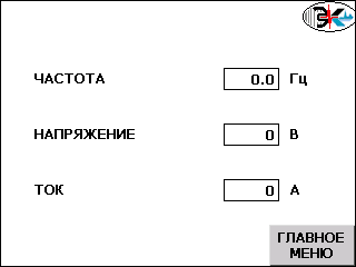
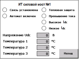
Touchbar (6 inches) has an operator menu of 15 screens, through which you can quickly monitor any node EK-AV6 and obtain performance values in real time. The control system has a log of 50 events, each of which records more than 80 parameters of the state of the system at the emergency moment (currents, voltages, active / reactive power, positions of discrete inputs / outputs, values of coefficients, etc.).
The use of a microprocessor control system with a touch panel and fiber-optic communication, as well as the use of low-voltage power modules, allows you to produce a high-tech RF, provide increased reliability and convenient maintenance.
 |
 |
|
Current inverter EK-AV6-4.0-SF-V6, 4000 kW, 6 kV Main touch panel screen |
Current inverter EK-AV6-4.0-SF-V6, 4000 kW, 6 kV The state screen of the power bridge No. 1 IT |
The company performs binding projects, supervision installation, equipment adjustment, warranty and post-warranty service, training of service personnel, technical advice on the choice of equipment. Delivery of equipment is carried out within 6-8 months from the date of conclusion of the contract and prepayment.